
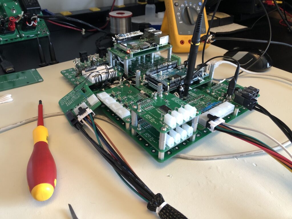
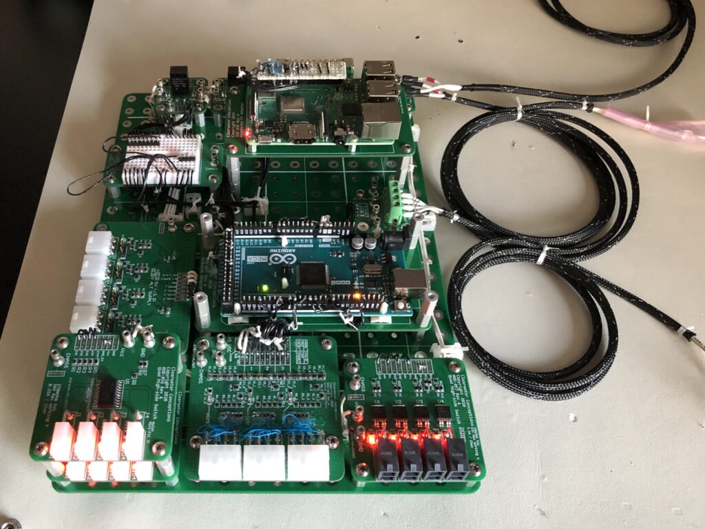
Multi-axis servo control system prototype. Made a mistake on one module – no big deal, because the others work great. Leaving only one sub-set of the system to be updated for the next prototype.
After each of these circuits are made sure to function well with the client’s equipment a custom PCB with all parts integrated together will be made with high-confidence. Meanwhile these modules can be used to prototype other designs or changes to the final product.
Due to the modular nature problems found during testing can be fixed more easily without having to potentially revision or populate a whole new PCB with all the circuits integrated on it. If one of the power drivers were to fail, for example, revising that module or bypassing it with another solution will be a lot easier and cleaner than trying to modify a PCB with the whole system on it.
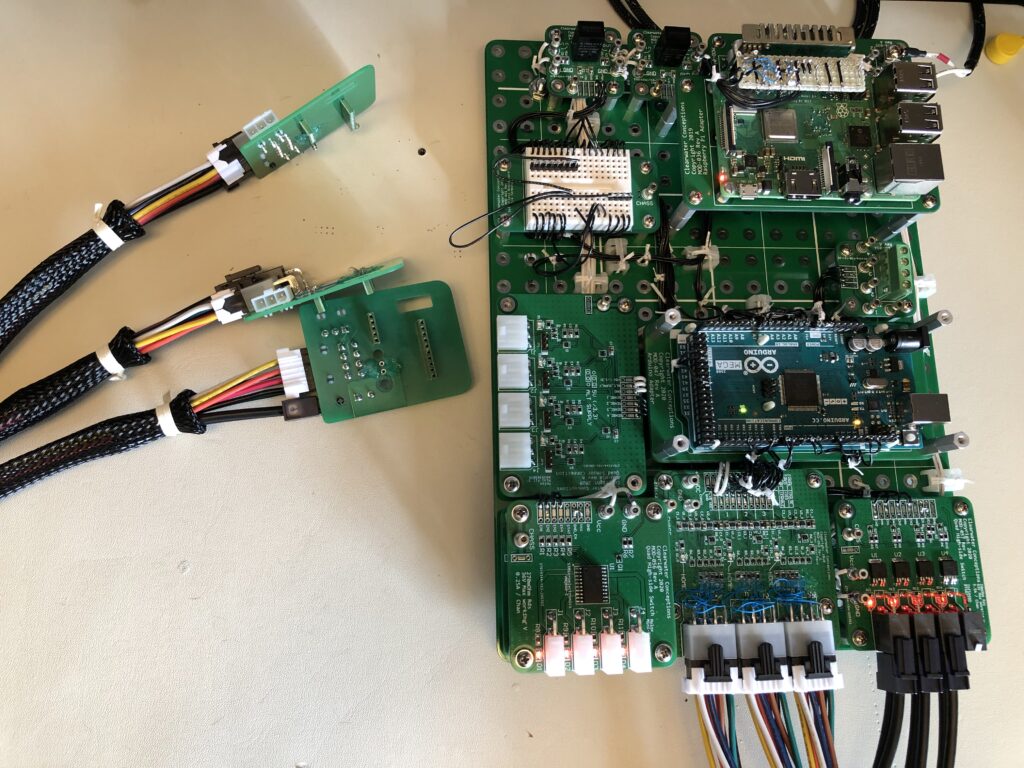
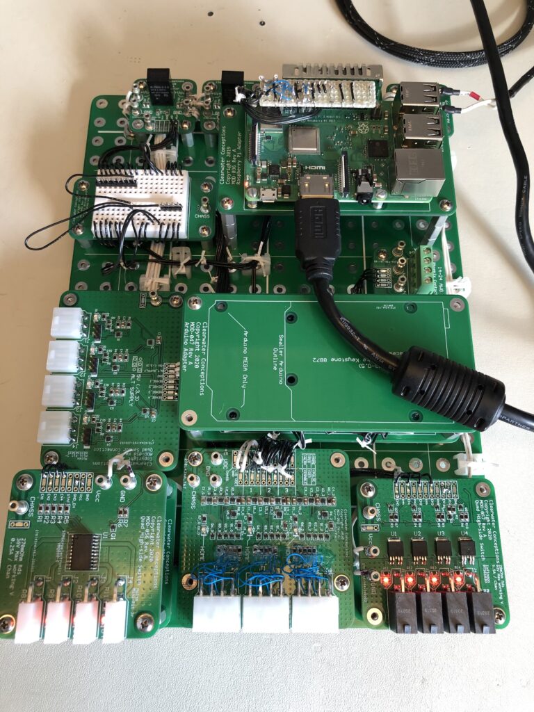
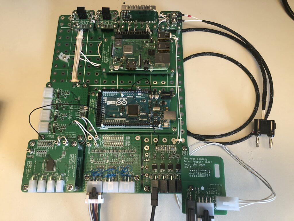
Overview of modules:
Top row are 3 DC-DC power supplies and a main 36V input. Voltage rails: 36V, 24V, 12V, 5V.
Raspberry Pi for UI and some general control (not hooked up yet).
(right middle) Arduino Mega for real-time control of up to 6 servos and multiple sensors. (only 3 servos for this initial prototype).
(left middle) 4-channel sensor input using 3-pin Molex Mini-Fit Jr connectors which supply power to the sensors and bring back the open-collector output of the sensors. Jumper-selection per-channel to select either 5V or a secondary power rail to go out to the sensor (in this case 24V). LED indicators for each channel. Based on discreet transistors, passives, and schmitt triggers.
(left bottom) 2x 4-channel solenoid drivers (stacked). This operate up to 36V and 0.25A per channel and use a highly-integrated high-side mosfet to reliably operate inductive loads. These use a 2-pin Molex Mini-Fit Jr connector per channel. LED indicators for each channel, status feedback, and overall disable for all channels. Based on VNQ860-E by STMicroelectronics.
(middle bottom) 3-channel servo interface which connects to up to 3 custom servo adapter boards using the same Molex Mini-Fit Jr series of connectors (8-pin in this case). Unfortunately a pinout mistake happened so I had to re-wire each connection on each pin in a different order. These provide buffering for signals going in and out of the servo motor (iHSS57-36-20 https://www.jmc-motor.com/product/973.html). This connects to the adapter board and also provides means to route back a signal for a homing sensor plus 5V power out to power the sensor. Based on discreet transistors, passives, and schmitt triggers.
(right bottom) 4-channel high-power high-side integrated switch for powering and turning on/off the servo motors. Using 2-pin Molex Mega-Fit connectors for higher power capability plus to ensure they don’t get mixed up with the 2-pin solenoid connectors. Based on BTS6163DAUMA1 by Infineon Technologies.
(far right bottom) servo adapter board which mounts in place of the discreet wiring connectors on the servo motor allowing ease of assembly, replacement, and routing of a homing sensor. Homing sensor connector uses the same 3-pin connector and pinout as the sensor input module. There is also an opening in the middle of the PCB to allow the LEDs of the servo to show through.