
With this design the client created a schematic and a basic drawing with the physical size, mounting hole locations, and rough positioning of connectors.
Functionality
The basic functionality of the final product is to take 16 channels of single-ended inputs (these come from hydrophones), have that input go to three separate differential amplifiers resulting in 3 differential outputs for each single-ended input. Each set of amplifiers has its own power supply with +/- 15V rails. The board is powered off of a single 5V input.
Iterations
We went through two iterations. Rev A used off the shelf DC-DC converters. It worked just fine. Though I had trouble finding a drawing with dimensions for the connectors and ended up making them too closely spaced. The connectors still fit, it was just inconvenient.
In Rev B the client took the time to roll his own DC-DC converters for the 5V -> +/- 15V conversion. I also had the physical connectors by then to measure and I think I may have found a drawing eventually that told me what they were supposed to be.
DFM (Design For Manufacturing)
I made improvements of my own (besides just better connector layout!) in Rev B.
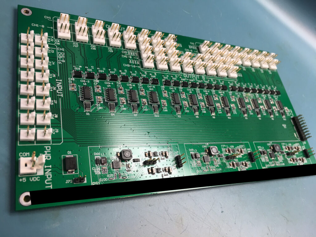
I added small pads right after the protection diodes (D18, D21…) allowing easy probing of the output signals while a connector is attached. I also added J66 on the far right exposing all of the 16 input signals allowing those to be easily measured. Some test points were also added within each of the 3 custom power supplies.
As you can see each part is clearly labeled both for end-user use (channel number, input section, output section, power input, etc) and for assembly and troubleshooting. Every part has a reference designator and times when there wasn’t room it was clearly indicated what reference designator is for what part. Each of the amplifiers is labeled for what channels they connect to making it trivial to troubleshoot and replace a blown amplifier if needed.
Challenges
The difficult aspect of this project for laying out the PCB is how I would want to go about distributing 16 channels to three separate sections. I ended up making a horizontal bus for each that then gets tapped off of for each of the three amplifiers that connects to it.
What I would do if there was a Rev C
If there was a Rev C, would route the differential outputs’ +/- right next to each other and reduce spacing between each channel (as far as I know there was no crosstalk issue for the client). I would also attempt to space out the single-ended bus more and get some ground stitching vias between them to provide a better fence between the channels. I would change the test points I put in to just small pads at most that could be easily probed or soldered to if needed, no need to install headers in them. I used a thermal relief design rule in Altium and forgot to make an exception/manual fix for the head pads underneath the DC-DC converter chips. (Before these boards shipped I believe I scraped away some solder mask around the pad and bypassed the thermal relief with some solder)
Summary
All in all I am very happy with this board. I think it looks great, laid out cleanly, and, of course, functions well.
Rev B top left 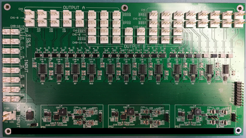
Rev B top 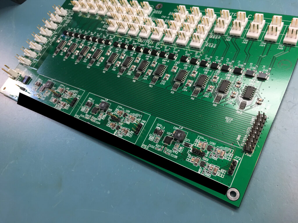
Rev B top right 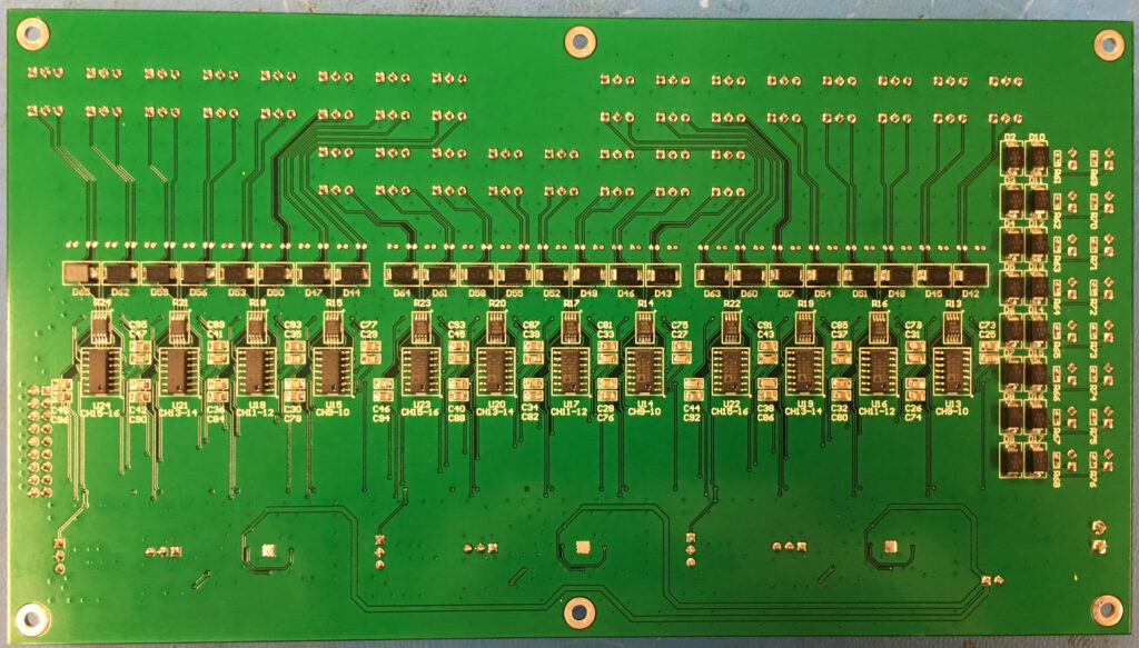
Rev B bottom 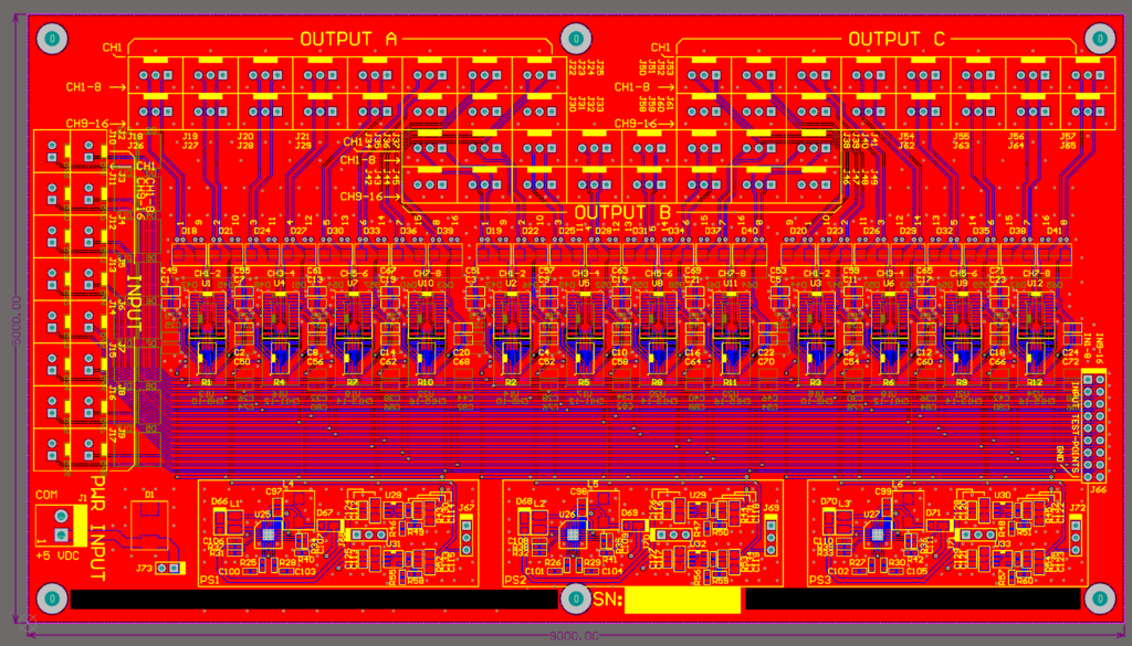
Rev B design screenshot 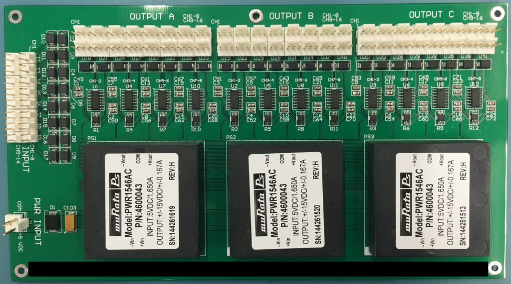
Rev A top 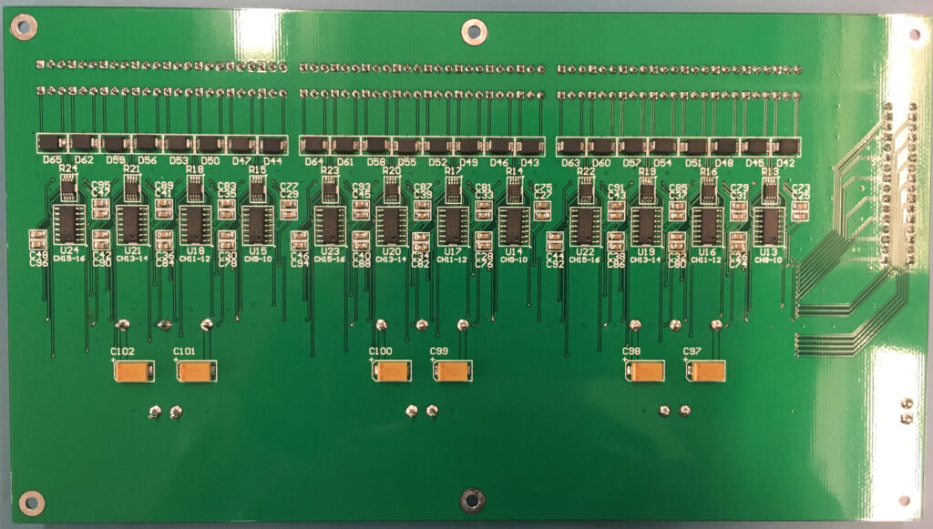
Rev A bottom 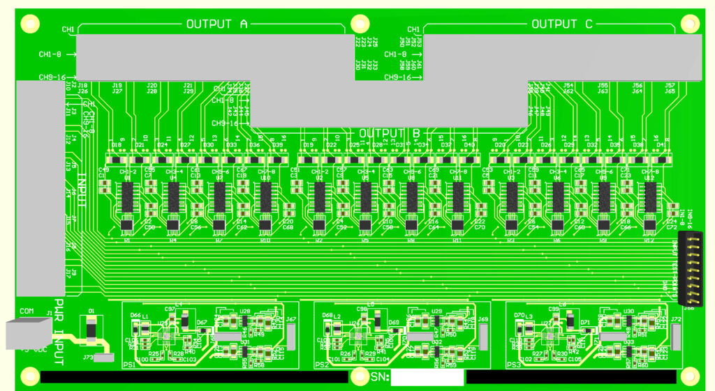
Rev B 3D render top 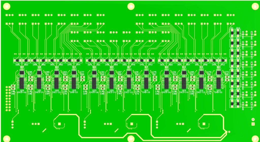
Rev B 3D render bottom